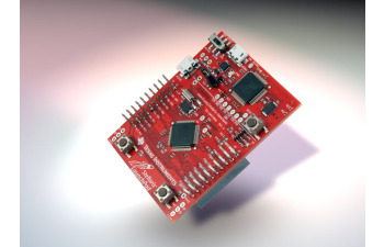
Both the Stellaris and TIVA launchpads have in-built USB VCP connections which can be used for debugging purposes. When the boards were connected to the PC we can see the COM ports appearing n the Device Manager. The post today will have a quick guide as how to use these to print some debug information. I have used the Stellaris launchpad for the experiment, but the TIVA launchpad also provides a similar interface.
By going through the schematics of the launchpads we can understand how the USB debug connection is made.

Here we can see that the UART0 of the IC is connected to the In-Circuit Debugger. UART0 means PA0 and PA1 pins, therefore we need to configure them in order to use this interface.
Following code will configure the UART0 and write a character to the console window.
<pre>	SysCtlPeripheralEnable(SYSCTL_PERIPH_UART0);
	SysCtlPeripheralEnable(SYSCTL_PERIPH_GPIOA);

	GPIOPinConfigure(GPIO_PA0_U0RX);
	GPIOPinConfigure(GPIO_PA1_U0TX);

	GPIOPinTypeUART(GPIO_PORTA_BASE, GPIO_PIN_0 | GPIO_PIN_1);

	UARTConfigSetExpClk(UART0_BASE, SysCtlClockGet(), 9600, (UART_CONFIG_WLEN_8 | UART_CONFIG_STOP_ONE | UART_CONFIG_PAR_NONE));

	UARTEnable(UART0_BASE);

        UARTCharPut(UART0_BASE, 'a');
Above code can be used to configure the UART0 interface and put the letter ‘a’ to the terminal window.
In order to make it more debug friendly I have created two functions, one for Init and another to display a string and a hex data value. It is very helpful when debugging firmware. More comprehensive library is available at ‘Stellarisware / Utils /’ directory with the name ‘uartstdio.c’. But it is quite large. This link will have a miniature version of the required components.
Currently I am using it for debugging purposes. Might come in handy to you too. If you come across any issue, put a comment here.
Thank you.
